![]()
| The Sphere tool is used to
create spheres anywhere in the work space. You will need to specify the drawing mode before you create the sphere. A polygonal sphere is represented using flat facets. |
|
A NURBS sphere is represented using curved facets and is in fact made up of two NURBS hemispheres. A NURBS sphere looks smoother than a polygonal one.
Usage:
1. Selecting the Sphere tool.
Click on the icon depicting the Sphere tool in the Tools Palette.
2. Positioning the origin of the reference axes.
Amapi 3D automatically positions the origin of the
reference axes at the Target Point. (See chapter User Manual/ Modeling help tools/ Control
panel/ Point of view/ Target Point.)
![]()
If you want to position the origin at a specific point in
the scene, place the Target Point on it. (See chapter User Manual/ Modeling help tools/
Control panel/ Point of view/ Target Point.)
3. Specifying the mode: NURBS or polygonal.
|
The Assistant Palette includes a “Modes” area displaying two buttons used to switch from one drawing mode to another. Make sure that the correct mode button is selected. Otherwise, click on it or use the hotkeys: PC: Ctrl+B, Mac: Command+B. |
4. Specifying the construction reference point.
The reference point will be either the top or bottom
point of the sphere.
There are two ways to specify it:
· Drag the cursor and
click.
Or
· Press the Tab key
and enter the point’s coordinates. Press the Return key to validate the entry.
5. Drawing the sphere.
| There are, here again, two
ways: · Drag the cursor toward the bottom or the top of the screen, to draw the sphere above or below the reference point. Click when you reach the desired size. Or · Press the Tab key and enter the radius value. Press the Return key to validate. In this case, the reference point will be the bottom of the sphere. |
|
6. Setting the number of points defining the sphere
| Once the sphere is created,
the “+/-” Tuner is displayed. Use it to make your sphere smoother or rougher. To tune, do any of the following: |
 |
· Press the
“+” and “-” keys of the numeric keypad.
· Click on the
“+” or “-” icons of the Assistant Palette.
· Press the Tab key
and enter a precise numerical value.
7. Ending the action.
Validate or put the tool aside to end the tool action (depending on the interface). See chapter User Manual/Generic use of a tool/How do you end a tool action?
| Practical exercises: · A Champagne cap/The cap’s head/Step 1 · A broken egg/Constructing the egg/Sphere creation |
| The Cube tool is used to
create cubes anywhere in the work space. The icon of the Cube tool is displayed at the top left corner of the screen while it is selected. |
|
The cube tool can create any rectangular 3D shape
defined by its numerical dimensions along the X, Y and Z axes.
A NURBS cube is displayed with grid lines to differentiate
it from a polygonal cube.
You will need to specify the drawing mode before creating
the cube.
Polygonal cube |
NURBS cube |
Usage:
1. Selecting the Cube tool.
Click on the icon depicting the Cube tool in the Tools Palette.
2. Positioning the origin of the reference axes.
Amapi 3D automatically positions the origin of the
reference axes at the Target Point. (See chapter User Manual/ Modeling help tools/ Control
panel/ Point of view/ Target Point.)
![]()
If you want to position the origin at a specific point in
the scene, place the Target Point on it. (See chapter User Manual/ Modeling help tools/
Control panel/ Point of view/ Target Point.)
3. Specifying the mode: NURBS or polygonal.
|
The Assistant Palette includes a “Modes” area displaying two buttons used to switch from one drawing mode to another. Make sure that the correct mode button is selected. Otherwise, click on it or use the hotkeys: PC: Ctrl+B, Mac: Command+B. |
4. Positioning the center of the base of the cube.
There are two ways to do this:
· Click on the
desired location.
Or
· Enter numerical
coordinates using the Tab key.
5. Creating the cube.
There are two ways to do this:
· Drag the cursor to
increase the cube’s size and click when you reach the correct size.
Or
· Press the Tab key
and enter the dimensions of your 3D cube. Press the Return key to validate the entry.
6. Ending the tool action.
![]()
The tool is automatically put aside and the Wand reappears.
| Practical exercises: · A little house/The little house’s body · A cone on a sloping plane/The sloping plane/Step 1 · An acoustic baffle/Draw the box/Step 1 · A playing card, a die and a token/Basic construction |
| Use the Grid tool to create a
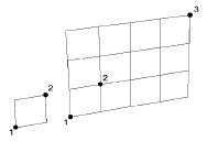
flat mesh. Then modify it using the modeling tools. A grid can be created either in polygonal mode or in NURBS mode. A NURBS grid looks different than a polygonal grid. A NURBS grid shows additional and smaller facets. You must specify the drawing mode before creating the grid. |
|
|
Usage:
1. Selecting the Grid tool.
Click on the icon depicting the Grid tool in the Tools Palette.
2. Positioning the origin of the reference axes.
Amapi 3D automatically positions the origin of the
reference axes at the Target Point. (See chapter User Manual/ Modeling help tools/ Control
panel/ Point of view/ Target Point.)
![]()
If you want to position the origin at a specific point in
the scene, place the Target Point on it. (See chapter User Manual/ Modeling help tools/
Control panel/ Point of view/ Target Point.)
3. Specifying the mode: NURBS or polygonal.
|
The Assistant Palette includes a “Modes” area displaying two buttons used to switch from one drawing mode to another. Make sure that the correct mode button is selected. Otherwise, click on it or use the hotkeys: PC: Ctrl+B, Mac: Command+B. |
4. Specifying a corner of the grid.
There are two ways to do this:
· Drag the cursor to
the desired location and click.
Or
· Press the Tab key
and enter the coordinates of the point. Press the Return key to validate the entry.
5. Setting the size of the facets of the mesh.
There are two ways to do this:
· Drag the cursor and
click when the facet has the desired size.
Or
· Press the Tab key
and enter the length and the height of the facet. Press the Return key to validate the
entry.
6. Setting the length and height of the grid.
There are two ways to do this:
· Move the cursor and
click when you reach the desired size.
Or
· Press the Tab key
and enter a value for U (number of horizontal facets) and V (the number of vertical
facets).

![]() You
will always have an integer number of facets. For instance, if each facet measures 10x10,
the length and height of the grid must each be a multiple of 10. For example, 180x50, not
182x47.
You
will always have an integer number of facets. For instance, if each facet measures 10x10,
the length and height of the grid must each be a multiple of 10. For example, 180x50, not
182x47.
7. Ending the tool action.
![]() The
tool is automatically put aside and the Wand cursor reappears.
The
tool is automatically put aside and the Wand cursor reappears.
| Practical exercises: · A house/The tiles/Step 4 · A tiled floor/Generating the tile floor/Step 1 |
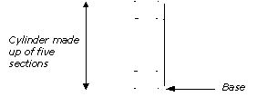
| The Cylinder tool is used to create a cylindrical 3D object quickly. |
|

The procedure followed to create a cylinder is exactly the same one as for creating a cone (see the “Cone” paragraph, following).
| Practical exercises: · A playing card, a die and a token/Basic construction |
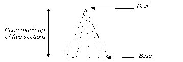
| The Cone tool is used to create a cone quickly. |
|

1. Selecting the Cone tool.
Click on the icon depicting the Cone tool in the Tools Palette.
2. Positioning the origin of the reference axes.
Amapi 3D automatically positions the origin of the
reference axes at the Target Point. (See chapter User Manual/ Modeling help tools/ Control
panel/ Point of view/ Target Point.)
![]()
If you want to position the origin at a specific point in
the scene, place the Target Point on it. (See chapter User Manual/ Modeling help tools/
Control panel/ Point of view/ Target Point.)
3. Selecting a mode: NURBS or polygonal.
|
Two buttons, displayed in the “Mode” area of the Assistant Palette, are used to switch mode. Check that the correct mode is selected. If not, click on the corresponding icon button or use the hotkeys: PC: Ctrl+B, Mac: Command+B. |
4. Specifying the cone orientation.
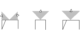
The orientation of the cone depends on the viewpoint selected at this stage. (See chapter User Manual/Control Panel/Views.)
Viewpoint selected at the creation
stage of the cone


Orientation of the cone in Front view
5. Specifying the center of the base.
The cursor switches to the Bullseye. Use it to specify
the center of the base of the cone.
There are two ways to do this:
· Drag the cursor to
the desired location and click.
Or
· Press the Tab key
and key in the numerical coordinates. Press the Return key to validate the entry.
6. Specifying the radius of the base.
There are two ways to specify the radius:
· Move the cursor and
click when the circle reaches the desired size.
Or
· Press the Tab key
and enter the precise radius of the circle. Press the Return key to validate the entry.
7. Specifying the height and the number of sections.
By default, the cone is defined by five sections.
However, you can specify a different number of sections.
· If you only need to
set the height, you can either:
· Drag the cursor
vertically and click when the cone reaches the desired height.
Or
· Press the Tab key
and enter the height numerically. Press the Return key to validate the entry.
· If you also need to set the number of sections, you can:
· Press the Tab
key and enter the height numerically.
· Press the Tab key
again and enter the number of sections. Press the Return key to validate the entry.
8. Specifying the number of points defining the base.
Once the basic cone is created, the “+/-”
Tuner is displayed, allowing you to modify the number of points defining the base. To do
so, you can:
· Press the
“+” and “-” keys of the numeric keypad.
· Click on the
“+” or “–” buttons of the Assistant Palette.
· Press the Tab key
and enter a precise number of points. Press the Return key to validate the entry.
9. Capping the base (optional).
By default, the base of the cone is open (it is
highlighted in red).
Go to the next step if you want to leave it open.
Click on it if you want to cap it.
10. Ending the tool action.
Validate or put the tool aside to end the tool action (depending on the interface). See chapter User Manual/Generic use of a tool/How do you end a tool action?
![]()